
Page 7 - 2014_FinishLine_Q4
P. 7
Volume 10, Issue 4 Page 7
MODAL IMPACT TESTING TECHNIQUES & USES By Christopher Sykora
This is the 1st in a two part series. Modal impact testing is one example of the experimental modal analysis techniques used to
find the natural frequencies of vibration of a structure. Impact testing uses an instrumented hammer to deliver an impulse force
to a structure while the vibrations are measured with other instrumentation. It is important to determine the natural frequen-
cies of turbomachinery structures like airfoils in order to be able to avoid matching the natural frequencies and the excitation
force frequencies from objects like stator & strut vane wakes. This is because resonance occurs when frequencies are matched
and vibrational energy significantly amplifies even small excitation forces to much higher levels, potentially causing high cycle
fatigue stresses. Although finite element analysis (FEA) is often used to simulate structure vibrations, the natural frequencies
can also be found experimentally with modal impact testing.
The typical equipment used for testing is the instrumented impact hammer to apply the force, a small accelerometer to record
the vibrations, an analog to digital signal converter, and signal analyzing software capable of converting the vibrations from the
time domain to the frequency domain. It is important to have a basic understanding of the proper setup and adjustments possi-
ble (such as frequency range, windowing, averaging, etc.) in the software in order to capture the correct data. Although modal
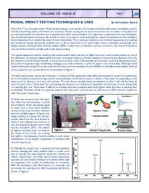
impact testing can be applied to any structure, the most common example of use at RMS is on individual rotor blades. Pictures
of the equipment and process flow are shown below in Figure 1.
The basic testing steps include the following: 1) Connect all the equipment with cables and adhesively mount the accelerome-
ter to the blade at a location of high motion during vibration. 2) Put the structure in either a “free state” by suspending it with
elastic cord or placing it on a very soft cushion. This will closely simulate being unrestrained so that it will vibrate freely all
over. Or put it into a “fixed state” by constraining the structure as it would be in operation. For the case of rotor blades held
in a spinning disc, the “fixed state” is difficult to simulate since the constraint gets much tighter when the rotor is spinning than
at assembly. Therefore, blades are typically tested in the “free state” and are used to calibrate to an FEA vibration model also
with “free state” constraints.
3) Strike the structure with the ham-
mer while the accelerometer records
the vibrations. Watch the impact signal
to make sure a very short duration
impulse force input has been achieved
and not a double impact. 4) Signal ana-
lyzing software processes the acceler-
ometer data from the time domain in
which it was collected and converts it
into the frequency domain with a Fast
Fourier Transform (FFT). The details
of signal processing math are beyond
the scope of this article, but viewing
the signal in the frequency domain enables a much easier
identification of the largest components of vibration (the
natural frequencies).
5) Typically the impact test is repeated and data gathered
without changing the setup multiple times in order to be
able to average the data together inside the software to
reduce “signal noise”. 6) Finally, the structure natural fre-
quencies are extracted by finding the locations of the high-
est responses from a plot of acceleration vs. frequency.
RMS has developed peak find macros to automate this
processing. An example plot with frequencies identified is
shown in Figure 2.